A DPMI/VCPI/XMS/RAW a system kernel extender.
Assembly 80×86 is used.
Open source
https://github.com/sdancer75/DOS4GigaBytes
A DPMI/VCPI/XMS/RAW a system kernel extender.
Assembly 80×86 is used.
Open source
https://github.com/sdancer75/DOS4GigaBytes
Protected mode is an operational mode of the Intel 80286-compatible CPU. It permits system software to use features such as virtual memory, paging and safe multi-tasking. It is also designed to increase the OS’s control over application software.
This term is also known as protected virtual address mode.
Intro
Protected mode was incorporated into Intel’s x86 architecture in early 1982. It then evolved into a basic foundation for all further Intel x86 architectures. The initial versions did not permit a switch back to real mode or enabling the protected mode. However, an option was provided to save the stack pointers, registers and interrupt mask in RAM through a keyboard controller. Later, with the advent of the 386 processor, protected mode could be enabled easily, eliminating complex steps involved in the 286 architecture, which did not have any internal mechanism to exit the protected mode.Protected mode provides several features to enhance system stability and security. These features are:
I remember when I was first learning protected mode. I had barely taught myself assembly language, and I got this crazy idea that I wanted to teach myself protected mode. I went out and purchased an 80286 assembly language book that included some protected mode examples, and I was off to learn. Within a few hours, I realized that the book I had purchased didn’t have any usable examples, since the examples in the book were intended to be programmed in EPROM CHIPS. So I hit the bulletin boards in search of something I could use as a guiding example.
The only example I found was so poorly documented and convoluted with task switching that even now, many years later, I haven’t figured it out. So with my IBM Technical Reference Manual and my 80286 book, I sat down and tried to figure out protected mode. After spending forty hours in three days of trying, I finally copied some source code out of the IBM Technical Reference Manual, and I was able to enter protected mode and then return to DOS.
Since that time, I have learned much about protected mode and how the CPU handles it internally. I discovered that the CPU has a set of hidden registers that are inaccessible to applications. I also learned how these registers get loaded, their role in memory management, and most importantly, their exact contents. Even though these registers are inaccessible, understanding the role they play in memory management can be applied to application’s programming. Applying this knowledge to programming can result in applications that use less data, less code, and execute faster.
PROTECTED MODE BASICSFrom an applications’ point of view, protected mode and real mode aren’t that different. Both use memory segmentation, interrupts, and device drivers to handle the hardware. But there are subtle differences that make porting DOS applications to protected mode non-trivial. In real mode, memory segmentation is handled automatically through the use of an internal mechanism, in conjunction with segment registers. The contents of these segment registers form part of the physical address that the CPU presents on the address bus (see figure 1a). The physical address is generated by multiplying the segment register by 16, then adding a 16-bit offset. Using 16-bit offsets implicitly limits the CPU to 64k segment sizes. Some programmers have programmed around this 64k segment size limitation by incrementing the contents of the segment registers. Their programs can point to 64k segments in 16-byte increments. Any program using this technique in protected mode would generate an exception (CPU-generated interrupt) — since segment registers aren’t used in the same manner. In protected mode, memory segmentation is defined by a set of tables (called descriptor tables) and the segment registers contain pointers into these tables. Each table entry is 8-bytes wide; therefore the values contained in the segment registers are defined in multiples of 8 (08h, 10h, 18h, etc.). The lower three bits of the segment register are defined, but for simplicity’s sake, let’s say that any program that loads a segment register with a value that isn’t a multiple of 8 will generate a protection error. There are two types of tables used to define memory segmentation: the Global Descriptor Table (GDT), and the Local Descriptor Table (LDT). The GDT contains segmentation information that all applications can access. The LDT contains segmentation information specific to a task or program. As previously mentioned, segment registers don’t form part of the physical address in protected mode, but instead are used as pointers to table entries in the GDT or LDT (see figure 1b). Each time a segment register is loaded, the base address is fetched from the table entry and stored in an internal, programer-invisible, register called the “segment descriptor cache.” The physical address presented on the CPU address bus is formed by adding the 16 or 32-bit offset to the base address in the descriptor cache. Another major concern for porting real-mode applications to protected mode is the use of interrupts. In real mode, double-word pointers to interrupt routines lie at physical address 0 (‘386 specific: unless the IDTR has been changed).Figure 4a illustrates interrupt service addressing in real mode. When an interrupt is called or generated, the CPU looks up the address of the Interrupt Service Routine (ISR) in this interrupt vector table. After the CPU pushes the flags on the stack, it performs a far call to the address in the table. The information pushed on the stack is the same for software, hardware, or CPU generated interrupts. In protected mode, the information pushed on the stack can vary, as can the base address of the interrupt vector table and the size of the interrupt table. The interrupt vector look up mechanism is also quite different from its real-mode counterpart. Figure 4bshows how interrupts are called from protected mode. After an interrupt is generated, the CPU compares the interrupt number (x8) against the size of the IDT — stored in the interrupt descriptor cache register. If the INT# x 8 doesn’t exceed the IDT size, then the interrupt is considered invokable, and the IDT base address is fetched from the descriptor cache; then the ISR’s protected mode address is fetched from the IDT. The ISR’s address is not a physical address but a protected mode, segmented address. Using the segment selector specified in the IDT, the CPU must perform the same limit-checking process again on the GDT to calculate the physical address of the ISR. Once the physical address is calculated, the CPU pushes the FLAGS, SEGMENT (selector), OFFSET, and possibly an ERROR CODE on the stack before branching to the ISR. ISRs for software and hardware interrupts needn’t be any different from their real-mode counterparts, but ISRs to service CPU generated interrupts and faults must be different. The CPU generates three categories of interrupts: traps, faults, and aborts. The stack image varies from category to category, as an error code may, or may not, be pushed on the stack. Traps never push an error code; faults usually do; and aborts always do. Traps are similar to and include software interrupts. This type of interrupt is appropriately named, as the CPU is “trapping” the occurrence of an event. The CPU doesn’t know the event occurred until after the fact; thus it must trap the event before signalling the interrupt. Therefore, the return address of these ISR’s point to instruction following the occurrence of the event. Traps include division by 0, data breakpoints, and INT03. Faults occur because something went wrong — something that should be fixed. The CPU knows instantly that something is wrong and signals the interrupt-generating mechanism. The primary purpose of this type of ISR, is to correct the problem and restart the program exactly where it left off. For this reason, the return address of the ISR points to the faulting instruction — thus making the fault restartable. Aborts are the most severe type of interrupt and are considered non-restartable. An error code is pushed on the stack, but will always be 0. The CPU’s stack segment, and state machines, may be in an I used to wonder why the BIOS can’t be used in protected mode. At that time, I thought it would be easy to write mode-independent code: just don’t do any FAR JUMPs, or FAR CALLS. But it’s not as simple as following these conventions. In addition to avoiding the use of far jumps and calls, the ISR must remove any error code pushed on the stack. This is where the impossibilities begin. Since the error code is placed on the stack only in protected mode, we need to detect whether or not we are in protected mode before the error code is removed. To determine this, we need access to the machine status work (MSW), or the system register CR0. Accessing the MSW can be done in any priviledge level, but accessing CR0 can only be done at the highest privilege level — level 0. If the user program is executing at any level less than 0, then we might not be able to access these registers. It can be done through the use of a special call gate that allows us to switch privilege levels before calling the ISR. This isn’t needed if we use the SMSW instruction. But even with that problem solved, let’s suppose the program left a real-mode value in any one of the segment registers. If the ISR pushes and subsequently pops any of these registers, the pop will cause the CPU to look for a selector in the GDT, or LDT. More than likely, using a real-mode value will cause a protection error. Therefore, using the BIOS in protected mode is nearly impossible. If there were a defined set of rules (a standard) that all programmers and operating systems followed, it could be done. |
Figure 4(a) — Interrupt service addressing in Real Mode Fig 4(b) Interrupt service addressing in Protected Mode
|
||||||||||||||||||||||||||||||||||||
Our goal is to enter protected mode, and leave protected mode and return to DOS. The ‘286 has no internal mechanism to exit protected mode: once you are in protected mode, you are there to stay. IBM recognized this, and implemented a hardware solution that would take the ‘286 out of protected mode by resetting the CPU. Since the power-on state of the ‘286 is real mode, simply resetting the CPU will return to real mode. But this introduces a slight problem, as the CPU won’t continue executing where it left off. At reset, the CPU starts executing at the top of memory, in the BIOS. Without a protocol to tell the BIOS that we reset the CPU for the purpose of exiting protected mode, the BIOS would have no way to return control back to the user program. IBM implemented a very simple protocol by writing a code to CMOS RAM (CMOS) where the BIOS can check this code and decide what to do. Immediately after the BIOS starts executing from the reset vector, it checks this code in CMOS to determine if the CPU was reset for the purpose of exiting protected mode. Depending on the code in CMOS, the BIOS can return control back to the user program and continue executing.
Resetting the CPU isn’t without its ramifications; all the CPU registers are destroyed, and the interrupt mask in the Programmable Interrupt Controller (PIC) is sometimes re-programmed by the BIOS (depending on the shutdown type). Therefore, it is the program’s responsibility to save the PIC mask, stack pointer, and return address before entering protected mode. The PIC mask and stack pointer must be stored in the user’s data segment, but the return address must be stored at a fixed location defined in the BIOS data segment — at 40:67h.
Next, we set the code in CMOS that tells BIOS we will exit protected mode and return to the user’s program. This is simply done by writing a value to the two CMOS I/O ports. After the CPU gets reset, and BIOS checks the CMOS code, BIOS will clear the CMOS code, so subsequent resets won’t cause unexpected results. After setting the code in CMOS, the program must build the GDT. (See the appropriate Intel programmer’s reference manual for a description of the GDT.) The limit, and access rights may be filled in by the compiler, as these values are static. But the base addresses of each segment aren’t known until run-time; therefore the program must fill them in the GDT. Our program will build a GDT containing the code, data, and stack segments addressed by our program. One last GDT entry will point to 1M for illustrative purposes.
Accessing memory at 1M isn’t as simple as creating a GDT entry and using it. The 8086 has the potential to address 64k (minus 16 bytes) beyond the maximum addressability of 1M — all it lacks is a 21st address line. The 8086 only has 20 address lines (A00..A19), and any attempt to address beyond 1M will wrap around to 0 because of the absence of A20. The ‘286 has 24 bits of addressability (A00..A23) and doesn’t behave like the 8086 in this respect. Any attempt to address beyond 1M (FFFF:0010 – FFFF:FFFF) will happily assert A20, and not wrap back to 0. Any program that relies on the memory wrapping “feature” of the 8086, will fail to run properly. As a solution to this compatibility problem, IBM decided to AND the A20 output of the CPU with a programmable output pin on some chip in the computer. The output of the AND gate is connected to the address bus, thus propogating or not, A20. Based on the input from the CPU A20, ANDed with an externally programmable source, address bus A20 gets asserted. The keyboard controller was chosen as this programmable source because it contained some available pins that can be held high, low, or toggled under program control. When the output of this pin is programmed to be high, the output of the AND gate is high when the CPU asserts A20. When the output is low,A20 is always low on the address bus — regardless of the state of the CPU A20. Thus by inhibiting A20 from being asserted on the address bus, ‘286- class machines can emulate the memory wrapping attributes of their 8086 predecessors.
Notice that only A20 is gated to the address bus. Therefore, without enabling the input to the A20 gate, the CPU can address every even megabyte of memory as follows: 0-1M, 2-3M, 4-5M, etc. In fact, duplicates of these memory blocks appear at 1-2M, 3-4M, 5-6M, etc. as a result of holding A20 low on the address bus. To enable the full 24-bits of addressability, a command must be sent to the keyboard controller (KBC). The KBC will enable the output on its pin to high, as input to the A20 gate. Once this is done, memory will no longer wrap, and we can address the full 16M of memory on the ‘286, or all 4G on 80386-class machines. All that remains in order to enter protected mode is changing the CPU state to protected mode and jumping to clear the prefetch queue (not necessary on the Pentium).
The following table summarizes the steps required to enter (with the intention of leaving) protected mode on the ‘286:
Steps 1-6 can be done in any order.
The minimum number of steps required to enter protected mode on the ‘386 and ‘486 are far fewer, as the ‘386 can exit protected mode without resetting the CPU. For compatibility purposes, all ‘386 BIOS’s will recognize the CPU shutdown protocol defined on ‘286-class machines, but following this protocol isn’t necessary. To exit protected mode on a ‘386, the program simply clears a bit in a CPU control register. There is no need to save the PIC mask, SS:SP, a return address, or set a CMOS code. The requisite steps for entering protected mode on a ‘386 simply become:
Of these requisite steps, building the GDT is the only step that may differ. In the ‘386 the base address is expanded to 32-bits, the limit is expanded to 20-bits, and two more control attribute bits are present. Listing 1 lists all the auxiliary subroutines to enter protected mode.
Like entering protected mode, exiting it differs from the ‘286 to 80386-class machines. The ‘386 simply clears a bit in the CPU control register CR0, while the ‘286 must reset the CPU. Resetting the CPU isn’t without its costs, as many hundred — if not thousands — of clock cycles pass in the time it takes to reset the CPU and return control back to the use program. The original method employed by IBM used the keyboard controller by connecting another output pin to the CPU RESET line. By issuing the proper command, the KBC would toggle the RESET line on the CPU. This method works, but it is very slow. Many new generation ‘286 chip sets have a “FAST RESET” feature. These chip sets toggle the RESET line by simply writing to an I/O port. When available, FAST RESET is the preferred method. But there is a third, obscure, but efficient method for resetting the CPU without using the KBC or FAST RESET. This method is elegant, faster than using the KBC, and works on the ‘386 WITHOUT resetting the CPU! It is truly the most elegant, comprehensive way to exit protected mode, since it works on both the ‘286, and ‘386 — in the most efficient way possible for each CPU. Listing 2 provides the code necessary to use the KBC and this elegant technique.
Using the KBC to reset the CPU is a straightforward technique, but in order to understand the elegant technique, some explanation is required. Recall that in our discussion of interrupts, the CPU checks the interrupt number (x8) against the limit field in the interrupt descriptor cache register (IDTR). If this test passes, then the next phase of interrupt processing begins. But if the test fails, then the CPU generates a DOUBLE FAULT (INT08). For example, let us suppose the limit field in the IDTR=80h: our IDT will service 16 interrupts, 00-15. If interrupt 16 or above was generated, the CPU would DOUBLE FAULT because a fault was generated at the inception of the interrupt calling sequence. Now, suppose the limit field in the IDTR=0, thus inhibiting all interrupts from being serviced. Any interrupt generation would cause the DOUBLE FAULT. But the DOUBLE FAULT itself would cause a fault, due to the limit being less than 40h. This ultimately would cause a TRIPLE FAULT, and the CPU would enter a shutdown cycle. The shutdown cycle doesn’t reset the CPU, as a shutdown cycle is considered a BUS cycle. External hardware is attached to the CPU to recognize the shutdown cycle. When a shutdown cycle is observed, the external hardware toggles the RESET input of the CPU. Therefore, all we need to do to cause the RESET is set the IDTR.LIMIT=0, then generate an interrupt. For elegance, we don’t just INT the CPU, we generate an invalid opcode. Our opcode is a carefully chosen opcode that doesn’t exist on the ‘286, but does exist on the ‘386. The elegance in the algorithm is in the opcode chosen for this purpose: MOV CR0,EAX. This will generate the desired invalid opcode exception on the ‘286, but is the first instruction in a sequence to exit protected mode on the ‘386. Thus the ‘286 gets RESET, and the ‘386 falls through and exits protected mode gracefully.
Exiting protected mode on the ‘286, and ‘386 closely resemble reversing the steps for entering protected mode. On the ‘286, you must:
And on the ‘386, the steps are simply:
(Listing 3 includes the subroutines needed to restore the machine state after exiting protected mode).
Notice that exiting protected mode on the ‘386 requires loading the segment registers twice. The segment registers are loaded the first time to assure that real-mode compatible values are stored in the hidden descriptor cache registers — as the descriptor cache registers “honor” the access attributes, and segment size limit, from protected mode, even when loaded in real mode. The segment registers are loaded the second time to define them with real-mode segment values.
Now that we have all the tools and theory necessary to enter and exit protected mode, we can apply this knowledge to write a program that enters protected mode, moves a block of data from extended memory, and exits protected mode — returning to DOS. Listing 4 shows a program that consists of these basic steps and can be used to move a 1k block of data from 1M to our program’s data segment.
Applications programming for real mode and protected mode aren’t that different. Both modes use memory segmentation, interrupts, and device drivers to support the hardware. Whether in real mode or protected mode, a set of user-inaccessible registers — called descriptor cache registers — play a major role in memory segmentation and memory management. The descriptor cache registers contain information defining the segment base address, segment size limit, and segment access attributes, and are used for all memory references — regardless of the values in the segment registers.
Entering and exiting protected mode requires nothing more than following the mechanics necessary for the proper mode transition: entering protected mode requires saving the machine state that needs to be restored upon exiting protected mode. The mechanics of entering real mode depend on the type of the CPU: the ‘286 requires a reset to enter real mode, and the ‘386 can enter real mode under program control. By applying our knowledge of how the CPU internally operates, we can write source code that exits protected mode in the manner best suited, and most elegant, for the given CPU.
Before we dive further, let’s quickly recap how these two authentication systems work. If you are already familiar with how cookie and token authentication works, feel free to skip this section, otherwise read on for an in-depth overview.
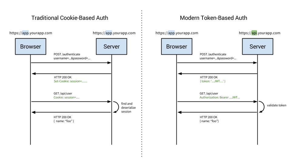
This diagram is a great introduction and simplified overview of the difference between cookie and token approaches to authentication.
Cookie based authentication has been the default, tried-and-true method for handling user authentication for a long time.
Cookie based authentication is stateful. This means that an authentication record or session must be kept both server and client-side. The server needs to keep track of active sessions in a database, while on the front-end a cookie is created that holds a session identifier, thus the name cookie based authentication. Let’s look at the flow of traditional cookie based authentication:
Token-based authentication has gained prevalence over the last few years due to rise of single page applications, web APIs, and the Internet of Things (IoT). When we talk about authentication with tokens, we generally talk about authentication with JSON Web Tokens (JWTs). While there are different ways to implement tokens, JWTs have become the de-facto standard. With this context in mind, the rest of the article will use tokens and JWTs interchangeably.
Token-based authentication is stateless. The server does not keep a record of which users are logged in or which JWTs have been issued. Instead, every request to the server is accompanied by a token which the server uses to verify the authenticity of the request. The token is generally sent as an addition Authorization header in form of Bearer {JWT}, but can additionally be sent in the body of a POST request or even as a query parameter. Let’s see how this flow works:
Understanding how something works is only half the battle. Next, we’ll cover the reasons why token authentication is preferable over the traditional cookie based approach.
Perhaps the biggest advantage to using tokens over cookies is the fact that token authentication is stateless. The back-end does not need to keep a record of tokens. Each token is self-contained, containing all the data required to check its validity as well as convey user information through claims.
The server’s only job then, becomes to sign tokens on a successful login request and verify that incoming tokens are valid. In fact, the server does not even need to sign tokens. Third party services such as Auth0 can handle the issuing of tokens and then the server only needs to verify the validity of the token.
Cookies work well with singular domains and sub-domains, but when it comes to managing cookies across different domains, it can get hairy. In contrast, a token-based approach with CORS enabled makes it trivial to expose APIs to different services and domains. Since the JWT is required and checked with each and every call to the back-end, as long as there is a valid token, requests can be processed. There are a few caveats to this and we’ll address those in the Common Questions and Concerns section below.
With a cookie based approach, you simply store the session id in a cookie. JWT’s on the other hand allow you to store any type of metadata, as long as it’s valid JSON. The JWT spec specifies different types of claims that can be included such as reserved, public and private. You can learn more about the specifics and the differences between the types of claims on the jwt.io website.
In practice, what this means is that a JWT can contain any type of data. Depending on your use case you may choose to make the minimal amount of claims such as the user id and expiration of the token, or you may decide to include additional claims such as the users email address, who issued the token, scopes or permissions for the user, and more.
When using the cookie based authentication, the back-end has to do a lookup, whether that be a traditional SQL database or a NoSQL alternative, and the roundtrip is likely to take longer compared to decoding a token. Additionally, since you can store additional data inside the JWT, such as the users permission level, you can save yourself additional lookup calls to get and process the requested data.
For example, say you had an API resource /api/orders that retrieves the latest orders placed via your app, but only users with the role of admin have access to view this data. In a cookie based approach, once the request is made, you’d have one call to the database to verify that the session is valid, another to get the user data and verify that the user has the role of admin, and finally a third call to get the data. On the other hand, with a JWT approach, you can store the user role in the JWT, so once the request is made and the JWT verified, you can make a single call to the database to retrieve the orders.
Modern APIs do not only interact with the browser. Written properly a single API can serve both the browser and native mobile platforms like iOS and Android. Native mobile platforms and cookies do not mix well. While possible, there are many limitations and considerations to using cookies with mobile platforms. Tokens on the other hand are much easier to implement on both iOS and Android. Tokens are also easier to implement for Internet of Things applications and services that do not have a concept of a cookie store.
In this section, we’ll take a look at some common questions and concerns that frequently arise when the topic of token authentication comes up. The key focus here will be security but we’ll examine use cases concerning token size, storage and encryption.
The biggest disadvantage of token authentication is the size of JWTs. A session cookie is relatively tiny compared to even the smallest JWT. Depending on your use case, the size of the token could become problematic if you add many claims to it. Remember, each request to the server must include the JWT along with it.
With token-based auth, you are given the choice of where to store the JWT. Commonly, the JWT is placed in the browsers local storage and this works well for most use cases. There are some issues with storing JWTs in local storage to be aware of. Unlike cookies, local storage is sandboxed to a specific domain and its data cannot be accessed by any other domain including sub-domains.
You can store the token in a cookie instead, but the max size of a cookie is only 4kb so that may be problematic if you have many claims attached to the token. Additionally, you can store the token in session storage which is similar to local storage but is cleared as soon as the user closes the browser.
Protecting your users and servers is always a top priority. One of the most common concerns developers have when deciding on whether to use token-based authentication is the security implications. Two of the most common attack vectors facing websites are Cross Site Scripting (XSS) and Cross Site Request Forgery (XSRF or CSRF).
Cross Site Scripting) attacks occur when an outside entity is able to execute code within your website or app. The most common attack vector here is if your website allows inputs that are not properly sanitized. If an attacker can execute code on your domain, your JWT tokens are vulnerable. Our CTO has argued in the past that XSS attacks are much easier to deal with compared to XSRF attacks because they are generally better understood. Many frameworks, including Angular, automatically sanitize inputs and prevent arbitrary code execution. If you are not using a framework that sanitizes input/output out-of-the-box, you can look at plugins like caja developed by Google to assist. Sanitizing inputs is a solved issue in many frameworks and languages and I would recommend using a framework or plugin vs building your own.
Cross Site Request Forgery attacks are not an issue if you are using JWT with local storage. On the other hand, if your use case requires you to store the JWT in a cookie, you will need to protect against XSRF. XSRF are not as easily understood as XSS attacks. Explaining how XSRF attacks work can be time consuming, so instead, check out this really good guide that explains in-depth how XSRF attacks work. Luckily, preventing XSRF attacks is a fairly simple matter. To over-simplify, protecting against an XSRF attack, your server, upon establishing a session with a client will generate a unique token (note this is not a JWT). Then, anytime data is submitted to your server, a hidden input field will contain this token and the server will check to make sure the tokens match. Again, as our recommendation is to store the JWT in local storage, you probably will not have to worry about XSRF attacks.
One of the best ways to protect your users and servers is to have a short expiration time for tokens. That way, even if a token is compromised, it will quickly become useless. Additionally, you may maintain a blacklist of compromised tokens and not allow those tokens access to the system. Finally, the nuclear approach would be to change the signing algorithm, which would invalidate all active tokens and require all of your users to login again. This approach is not easily recommended, but is available in the event of a severe breach.
A JSON Web Token is comprised of three parts: the header, payload, and signature. The format of a JWT is header.payload.signature. If we were to sign a JWT with the HMACSHA256 algorithm, the secret ‘shhhh’ and the payload of:
{
  "sub": "1234567890",
  "name": "Ado Kukic",
  "admin": true
}
The JWT generated would be:
eyJhbGciOiJIUzI1NiIsInR5cCI6IkpXVCJ9.eyJzdWIiOiIxMjM0NTY3ODkwIiwibmFtZSI6IkFkbyBLdWtpYyIsImFkbWluIjp0cnVlLCJpYXQiOjE0NjQyOTc4ODV9.Y47kJvnHzU9qeJIN48_bVna6O0EDFiMiQ9LpNVDFymM
The very important thing to note here, is that, this token is signed by the HMACSHA256 algorithm, and the header and payload are Base64URL encoded, it is not encrypted. If I go to jwt.io, paste this token and select the HMACSHA256 algorithm, I could decode the token and read its contents. Therefore, it should go without saying that sensitive data, such as passwords, should never be stored in the payload.
If you must store sensitive data in the payload or your use case calls for the JWT to be obscured, you can use JSON Web Encryption (JWE). JWE allows you to encrypt the contents of a JWT so that it is not readable by anyone but the server. JOSE provides a great framework and different options for JWE and has SDKs for many popular frameworks including NodeJS and Java. Anyway, I encourage you to learn more about AngularJS Authentication.
Here at Auth0, we’ve written SDKs, guides, and quickstarts for working with JWTs for many languages and frameworks including NodeJS, Java, Python, GoLang, and many more. Our last “Cookies vs. Tokens” article used the AngularJS framework, so it’s fitting to use Angular 2 for our code samples today.
You can download the sample code from our GitHub repo created by Kim Maida. Downloading the code samples is preferable as Angular 2 requires a lot of initial setup to get going. If you haven’t already, sign up for a free Auth0 account so you can do the implementation yourself and experiment with different features and options. Let’s get started.
The sample Angular application and API has the following features:
http://localhost:3001/api/dragons returns JSON data for authenticated GET requestshttp://localhost:4200/callback to the Allowed Callback URLs and http://localhost:4200 to the Allowed Origins (CORS).RS256.http://localhost:3001/api/. The Signing Algorithmshould be RS256.We’re now ready to implement Auth0 authentication on both our Angular client and Node backend API.
The Angular app utilizes the Angular CLI. Make sure you have the CLI installed globally:
$ npm install -g @angular/cli
Once you’ve cloned the project, install the Node dependencies for both the Angular app and the Node server by running the following commands in the root of your project folder:
$ npm install
$ cd server
$ npm install
The Node API is located in the /server folder at the root of our sample application.
Open the server.js file:
// server/server.js
...
// @TODO: change [CLIENT_DOMAIN] to your Auth0 domain name.
// @TODO: change [AUTH0_API_AUDIENCE] to your Auth0 API audience.
var CLIENT_DOMAIN = '[CLIENT_DOMAIN].auth0.com';
var AUTH0_AUDIENCE = '[AUTH0_API_AUDIENCE]';  // http://localhost:3001/api in this example

var jwtCheck = jwt({
    secret: jwks.expressJwtSecret({
      cache: true,
      rateLimit: true,
      jwksRequestsPerMinute: 5,
      jwksUri: `https://${CLIENT_DOMAIN}/.well-known/jwks.json`
    }),
    audience: AUTH0_AUDIENCE,
    issuer: `https://${CLIENT_DOMAIN}/`,
    algorithms: ['RS256']
});
...
//--- GET protected dragons route
app.get('/api/dragons', jwtCheck, function (req, res) {
  res.json(dragonsJson);
});
...
Change the CLIENT_DOMAIN variable to your Auth0 client domain and AUTH0_AUDIENCE to whatever you set your API audience to. The /api/dragonsroute will be protected with express-jwt and jwks-rsa.
Note: To learn more about RS256 and JSON Web Key Set, read Navigating RS256 and JWKS.
Our API is now protected, so let’s make sure that our Angular application can also interface with Auth0. To do this, we’ll activate the src/app/auth/auth0-variables.ts.example file by deleting the .example from the file extension. Then open the file and change the [CLIENT_ID] and [CLIENT_DOMAIN] strings to your Auth0 information:
// src/app/auth/auth0-variables.ts
...
export const AUTH_CONFIG: AuthConfig = {
  CLIENT_ID: '[CLIENT_ID]',
  CLIENT_DOMAIN: '[CLIENT_DOMAIN].auth0.com',
  ...
Our app and API are now set up. They can be served by running $ ng servefrom the root folder and $ node server.js from the /server folder.
With the Node API and Angular app running, let’s take a look at how authentication is implemented.
Authentication logic on the front end is handled with an AuthServiceauthentication service: src/app/auth/auth.service.ts file.
import { Injectable } from '@angular/core';
import { Router } from '@angular/router';
import { BehaviorSubject } from 'rxjs/BehaviorSubject';
import { AUTH_CONFIG } from './auth0-variables';
import { tokenNotExpired } from 'angular2-jwt';
import { UserProfile } from './profile.model';

// Avoid name not found warnings
declare var auth0: any;

@Injectable()
export class AuthService {
  // Create Auth0 web auth instance
  // @TODO: Update AUTH_CONFIG and remove .example extension in src/app/auth/auth0-variables.ts.example
  auth0 = new auth0.WebAuth({
    clientID: AUTH_CONFIG.CLIENT_ID,
    domain: AUTH_CONFIG.CLIENT_DOMAIN
  });

  userProfile: UserProfile;

  // Create a stream of logged in status to communicate throughout app
  loggedIn: boolean;
  loggedIn$ = new BehaviorSubject<boolean>(this.loggedIn);

  constructor(private router: Router) {
    // If authenticated, set local profile property and update login status subject
    if (this.authenticated) {
      this.userProfile = JSON.parse(localStorage.getItem('profile'));
      this.setLoggedIn(true);
    }
  }

  setLoggedIn(value: boolean) {
    // Update login status subject
    this.loggedIn$.next(value);
    this.loggedIn = value;
  }

  login() {
    // Auth0 authorize request
    // Note: nonce is automatically generated: https://auth0.com/docs/libraries/auth0js/v8#using-nonce
    this.auth0.authorize({
      responseType: 'token id_token',
      redirectUri: AUTH_CONFIG.REDIRECT,
      audience: AUTH_CONFIG.AUDIENCE,
      scope: AUTH_CONFIG.SCOPE
    });
  }

  handleAuth() {
    // When Auth0 hash parsed, get profile
    this.auth0.parseHash((err, authResult) => {
      if (authResult && authResult.accessToken && authResult.idToken) {
        window.location.hash = '';
        this._getProfile(authResult);
        this.router.navigate(['/']);
      } else if (err) {
        this.router.navigate(['/']);
        console.error(`Error: ${err.error}`);
      }
    });
  }

  private _getProfile(authResult) {
    // Use access token to retrieve user's profile and set session
    this.auth0.client.userInfo(authResult.accessToken, (err, profile) => {
      this._setSession(authResult, profile);
    });
  }

  private _setSession(authResult, profile) {
    // Save session data and update login status subject
    localStorage.setItem('access_token', authResult.accessToken);
    localStorage.setItem('id_token', authResult.idToken);
    localStorage.setItem('profile', JSON.stringify(profile));
    this.userProfile = profile;
    this.setLoggedIn(true);
  }

  logout() {
    // Remove tokens and profile and update login status subject
    localStorage.removeItem('access_token');
    localStorage.removeItem('id_token');
    localStorage.removeItem('profile');
    this.userProfile = undefined;
    this.setLoggedIn(false);
  }

  get authenticated() {
    // Check if there's an unexpired access token
    return tokenNotExpired('access_token');
  }

}
This service uses the config variables from auth0-variables.ts to instantiate an auth0.js WebAuth instance.
Note:
auth0.jsis linked in theindex.htmlfile from CDN.
An RxJS BehaviorSubject is used to provide a stream of authentication status events that you can subscribe to anywhere in the app.
The login() method authorizes the authentication request with Auth0 using your config variables. An Auth0 hosted Lock instance will be shown to the user and they can then log in:
Note: If it’s the user’s first visit to our app and our callback is on localhost, they’ll also be presented with a consent screen where they can grant access to our API. A first party client on a non-localhost domain would be highly trusted, so the consent dialog would not be presented in this case. You can modify this by editing your Auth0 Dashboard API Settings. Look for the “Allow Skipping User Consent” toggle.
We’ll receive an id_token and an access_token in the hash from Auth0 when returning to our app. The handleAuth() method uses Auth0’s parseHash()method callback to get the user’s profile (_getProfile()) and set the session (_setSession()) by saving the tokens and profile to local storage and updating the loggedIn$ subject so that any subscribed components in the app are informed that the user is now authenticated.
Note: The profile takes the shape of
profile.model.tsfrom the OpenID standard claims.
The handleAuth() method can then be called in the app.component.tsconstructor like so:
// src/app/app.component.ts
import { AuthService } from './auth/auth.service';
...
  constructor(private auth: AuthService) {
    // Check for authentication and handle if hash present
    auth.handleAuth();
  }
...
Finally, we have a logout() method that clears data from local storage and updates the loggedIn$ subject. We also have an authenticated() accessor to return current authentication status.
Once AuthService is provided in app.module.ts, its methods and properties can be used anywhere in our app, such as the home component.
The callback component is where the app is redirected after authentication. This component simply shows a loading message until hash parsing is completed and the Angular app redirects back to the home page.
In order to make authenticated HTTP requests, we’re using angular2-jwt. The auth-http.factory.ts factory supplies an authHttp method that sends the access_token from local storage. This is provided in the app.module.ts file:
// src/app/app.module.ts
...
import { authHttpFactory } from './auth/auth-http.factory';
...
  providers: [
    ...,
    {
      provide: AuthHttp,
      useFactory: authHttpFactory,
      deps: [Http, RequestOptions]
    }
  ],
We can then call our API in the api.service.ts file with AuthHttp to authorize requests.
// src/app/api.service.ts
...
import { AuthHttp, AuthConfig } from 'angular2-jwt';
...
  getDragons$(): Observable<any[]> {
    return this.authHttp
      .get(`${this.baseUrl}dragons`)
      .map(this._handleSuccess)
      .catch(this._handleError);
  }
...
A profile page component can show an authenticated user’s profile information. However, we only want this component to be accessible if the user is logged in.
With an authenticated API request and login/logout implemented, the final touch is to protect our profile route from unauthorized access. The auth.guard.ts route guard can check authentication and activate routes conditionally. The guard is implemented on specific routes of our choosing in the app-routing.module.ts file like so:
// src/app/app-routing.module.ts
...
import { AuthGuard } from './auth/auth.guard';
...
      {
        path: 'profile',
        component: ProfileComponent,
        canActivate: [
          AuthGuard
        ]
      },
...
That’s it! We have an authenticated Node API and Angular application with login, logout, profile information, and protected routes. To learn more, check out the following resources:
In today’s article we compared the differences between cookie and token-based authentication. We highlighted the advantages and concerns of using tokens and also wrote a simple app to showcase how JWT works in practice. There are many reasons to use tokens and Auth0 is here to ensure that implementing token authentication is easy and secure. Finally, we introduced Progressive Web Apps to help make your web applications feel more native on mobile devices. Sign upfor a free account today and be up and running in minutes.